

Expert Consulted: Adrian Gardiner. I’m drawing on my own 30 years of experience in the IT industry to write this article, having built many new, refurbished, and upgraded computers for my customers. I’ve been asked to build both affordable and premium gaming computers, so I have good knowledge to share.
Building a gaming PC for under $1000 may sound like a challenge too far, but it’s definitely not. This budget gives us plenty of scope to put together a nice gaming build.
In this article, I explain the exact process of building your Gaming PC from start to finish.
This build puts the total budget towards the actual PC and does not include a monitor, mouse, and keyboard, which I’ve assumed you already have.
Related Articles:
How to Afford a Gaming PC in 5 Steps
The Top 45 PC Building Mistakes to Avoid
Building a Gaming PC for Under $1000 – Guide
The following steps will show you the exact steps to building your Gaming PC.
Required Tools
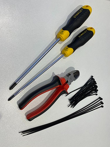
To build your PC, you’ll need the following tools:
- Phillips Screwdriver PH1 x 150 mm with magnetic tip (I use Stanley 0-64-933 cushion grip screwdriver)
- Phillips Screwdriver PH2 x 150 mm with magnetic tip (I use Stanley 0-64-941 cushion grip screwdriver)
- Wire Cutters (these make light work of snipping cable ties)
- Cable Ties 250 x 2.5 mm (minimum required 10+) Usually supplied in pack of 100
- Cable Ties 100 x 2.5 mm (minimum required 25+) Usually supplied in pack of 100
- A good torch or very good lighting that you can safely direct into the case (essential as you’ll really struggle to assemble the PC in poor light).
The Phillips screwdrivers need to be a decent length to make it easy to screw in the motherboard screws after you’ve placed the motherboard inside the case.
The magnetic tips on the end of the Phillips screwdrivers are very useful for placing screws inside the case during assembly or for retrieving screws that have got dislodged inside the case and would otherwise be very difficult to retrieve. You’ll thank me when using these!
You’ll need the cable ties to tidy up the wiring inside the computer case.
All of the above tools can be bought for very reasonable prices on Amazon.
PC Components
The exact components you’ll need for your PC are:
- Processor (CPU)
- CPU Cooler
- Motherboard
- Memory (RAM)
- Graphics Card (GPU)
- Power Supply (PSU)
- Case Fan(s) – usually, a rear and/or front fan will come with the case
- Case / Chassis
- Although not a physical component, we will, of course, need a Windows 11 license.
The motherboard will come with all screws necessary for the motherboard fitment, the PSU will come with its own 4 screws, and the case will usually have 4 screws securing both side panels (some cases have push-to-release panels).
Sourcing Components Under $1000
Now, we need to select our build components under $1000 in value.
NOTE: A monitor, mouse, and keyboard are not included in our build.
The easiest way to find your parts and stay within budget is to visit https://pcpartpicker.com/
At the time of writing, using pcpartpicker.com, the following parts can be purchased for just under $1000:
- Processor (CPU): Intel Core i7-12700K 3.6 GHz 12 Core Processor
- CPU Cooler: Thermalright Assassin X 120 Refined SE 66.12 CFM CPU Cooler
- Motherboard: Gigabyte B660M DS3H AX DDR4 Micro ATX LGA1700 Motherboard
- Memory (RAM): Corsair Vengeance LPX 16 GB (2 x 8 GB) DDR4-3200 CL16 Memory
- Storage: Kingston NV2 2 TB M.2-2280 PCIe 4.0 X4 NVME Solid State Drive
- Graphics Card (GPU): EVGA SC ULTRA GAMING GeForce GTX 1650 SUPER 4 GB Graphics Card
- Case / Chassis: Cougar MX330-G Air ATX Mid Tower Case
- Power Supply Unit (PSU): Thermaltake Smart BM2 550w 80+ Bronze Semi-Modular Power Supply Unit
- Operating System: Microsoft Windows 11 Home. Also, consider whether you want to stick with Windows 10.
If you wanted to spend more, I’d put it into a more powerful graphics card and maybe doubling up on RAM to 32 GB.
The parts chosen above or those chosen by you will, to some extent, affect some of the build processes below, covered in this article, like, for example:
- CPU – using an AMD processor will mean a slightly different install process
- CPU Cooler – it may have a slightly different install process
- Computer case – it may require a different way of installing the PSU.
Manuals/guides provided by the supplier should help with any differences in the installation process.
Putting It All Together
Now for the exciting bit – putting it all together!
Important Notes
- Make Space: Before doing anything, clear some good desk or table space away from any clutter for working on your PC. You’ll need quite a bit of room to lay everything out. If you have any sort of thin rubberized mat that you can use to cover the working space, that would be great, just to protect the desk/table from getting scratched. A tablecloth can be used if nothing else is available.
- Take Your Time: Whatever you do, don’t rush the build. Take as long as you need, and everything should go fine. Rush and mistakes will be made.
Static Electricity

The enemy of computer components is static electricity.
However, some simple steps taken can minimize any risk to your new computer parts.
- Wear an Anti-Static Wrist Strap to ground yourself while working on your PC ($6 on Amazon)
- Ideally, place the PC on a rubber anti-static mat on a hard surface
- Minimize the risk (low) of electrostatic shock (it can damage PC components) by grounding yourself before touching the inside of your PC case. You can do this by touching grounded metal objects (e.g., a water pipe) every few minutes
- Avoid standing on the carpet in socks (go barefoot on a hard floor), which will generate static electricity if you move your feet a lot.
Assembly

- Carefully remove both side panels using a screwdriver PH2 x 150 and put the screws somewhere safe.
- Remove the small bag of screws etc. from inside the case. Open the bag and lay the contents somewhere safe.
- Open the plastic bag containing the IO Shield.
- Fit the IO Shield to the case by clipping it into the same-sized slot at the inside rear of the case. I find by clipping one end of the shield first and holding that; you can then clip in the remaining bit. Make sure it’s the right way round – usually, three circular holes for sound connections are at the bottom. Check your motherboard to be sure.
- Carefully remove the motherboard from the box and its anti-static bag and lay it on top of the box.
- Note the position of each screw hole on the motherboard and match these with the standoff posts inside the case where the motherboard will be installed – they should match in number and position exactly. If there is a standoff missing, i.e., nowhere to screw in to, take a spare standoff from the small bag of screws that came with the case and fit to the case where required to enable the motherboard to be affixed. Use the standoff tool with a screwdriver to gently tighten.
CPU Installation
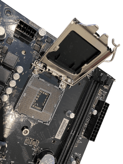
Firstly, I strongly recommend that you read the CPU installation guide provided in your motherboard manual before tackling this bit.
- Unhook the CPU locking arm and lift the CPU securing bracket up, ready to fit the CPU
- Very carefully remove the CPU from its plastic container, holding the CPU by the edges (do not touch the gold pins on the underside of the CPU).
- After noting the small arrow on one corner of the CPU and/or the two locating grooves, very carefully place the CPU into the CPU socket on the motherboard, aligning the arrow on the CPU with the corresponding arrow and raised nodules on the CPU socket. Lower the CPU carefully and gently – it should slot in very easily and will look completely flat in its socket.
NOTE: The CPU will only fit one way and should ‘not’ be forced, or damage will occur - Now, bring the CPU bracket back over the CPU and then move the locking arm into place to secure the CPU in position.
- Finally, remove the black temporary plastic CPU cover and store it for later use if the processor is ever removed – it just unclips easily.
Memory (RAM)
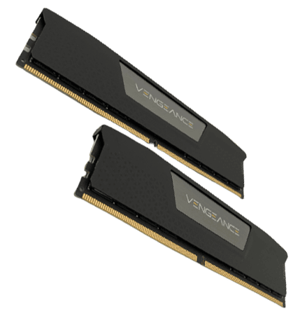
Next, we fit the RAM memory modules (dual inline memory modules or DIMM for short) – it’s easier to fit these before we attach the CPU Cooler.
- Rotate the motherboard so that you have the two memory slots facing you horizontally.
- For each of the two memory modules in this build, you hold each end of a DIMM between the fingers of each hand and carefully lower into the slot, taking note of the notch in the middle of the DIMM and the corresponding position of the raised portion of the slot.
- The position of the notch is not exactly central, meaning the contacts on each side of the notch are of noticeably different lengths. The DIMM only fits one way and must not be forced.
- Once a DIMM is located between the post at each end of the slot, push down at each end until you hear a click, holding the DIMM between two fingers to make sure that it doesn’t move around too much.
- Follow the same process for the remaining DIMM.
CPU Cooler
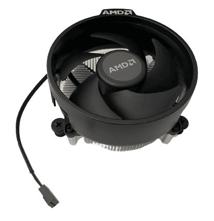
For this build, to keep the cost within budget, we’ll be using an air-cooled system, so we now need to fit the CPU heatsink with its integrated cooling fan.
We are also using an Intel processor. This installation process would be slightly different if using an AMD CPU, something to bear in mind if you decide to purchase a different processor.
- Remove the heatsink and fan assembly from its package, being careful to avoid touching the pre-applied thermal paste on the base of the heatsink.
- Unravel the fan power cable.
- Before fitting the heatsink/fan assembly, position it over the installed CPU and note the location of the 4-pin CPU_FAN header (noting how much of the fan cable you will need) and the 4 holes in the motherboard ready for the 4 locating posts on your heatsink/fan assembly – a dry run if you like.
- Now position the heatsink/fan assembly over the installed CPU again, making sure to orient it into a position that will give you enough cable length to reach the 4-pin CPU_FAN header.
- Slowly lower the heatsink/fan assembly onto the installed CPU, making sure that all four locating posts are in position over their respective sockets on the motherboard.
- When the heatsink/fan assembly is in place, and all 4 locating posts are resting in each socket, press down on each locating post in a diagonal method until each engages with a click, securing them in place.
- Now carefully slide the fan power cable over the CPU_FAN header – it will only fit one way.
- If there is a lot of slack in the fan cable, this can be tied back later with a cable tie.
Storage (M.2 NVMe SSD Drive)
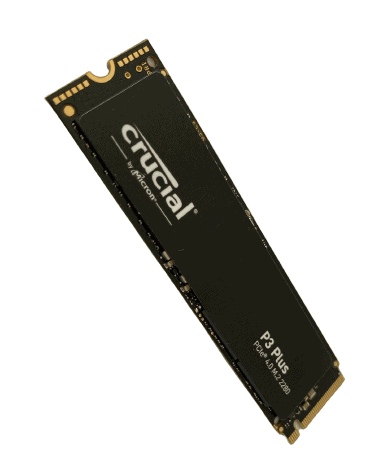
The next step is to install our SSD storage.
- Unpack your M.2 NVMe SSD ready for installation.
- Locate your M.2 NVMe slot on the motherboard and fix the screw in readiness for installation.
- Gently insert your M.2 SSD drive into the port on the motherboard until it is clearly seated (line up the notch on the SSD), and then bring down the other end of the drive until it is in contact with the seating/attachment post.
- Whilst holding the drive in place and using the PH1 screwdriver (putting the tiny screw on the end in readiness will just about work), carefully place the fixing screw in over the screw hole and very gingerly start tightening the screw to hold the SSD down in place. NOTE: Do not overtighten! Only tighten until you meet the smallest of resistance. This screw is very delicate, and you don’t want to round it off / damage the screw head and lose the ability to remove it in the future.
Motherboard
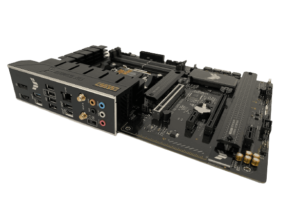
I find it much easier to connect the cables that come with the case before inserting/installing the motherboard. When the board has been placed inside the case it’s much harder to see some of the very small pin connectors that you will be connecting up – it’s very easy to damage these.
- Find a motherboard-sized piece of cardboard or thin foam (you may have some in the motherboard box), place this on the edge of the case (to protect it), and carefully lay the motherboard on top of it so that the cables will reach (the audio probably won’t reach at this stage as it has the furthest to go in the case).
- Connect the USB 3.0 header cable* to the header on the motherboard (this is the largest cable, and the connector is about 1″ wide. You’ll need to go very slow with this one as it is so very easy to bend the pins on the motherboard (I’ve done this!). Line it up very carefully (look for the notch) make sure it is square, and then give a firm push, and you’ll be fine.
- Attach the System Panel Header cables.* They are small and fiddly but not too difficult to fit. There are usually 4 or 5 of them comprising PLED+ and PLED-, PWRBTN, HDD_LED, and RESET.
- Attach the USB 2.0 cable* to its respective header on the motherboard.
- Now carefully lower the motherboard into the case and position it so that the ports on the top left of the motherboard line up with the holes on the IO Shield that we installed earlier and the screw holes with the stand-off posts.
- Gently holding the motherboard in place so that it doesn’t move around, have a quick look at the rear ports to make sure everything looks properly lined up from the outside and no port has been obscured by any metal. NOTE: I have often found that the HDMI port has a piece of metal designed to make contact that is bent out of shape slightly and can block the port – if this happens, gently bend the metal back a little so that it clears the port and then reseat the motherboard again.
- Now attach the motherboard carefully with the provided screws** using your long-barrelled, magnetic-tipped PH1 screwdriver. If you place the screw on the end of your screwdriver, it will stay there as you lower it into the case, allowing you to position it over the screw hole and start screwing it in. Do not overtighten – as soon as you feel a bit of resistance, that’s tight enough.
- Now attach the Audio cable by sliding it onto the HD_AUDIO* pin header – usually located at the bottom left of the case.
- Attach your case fan cables to the CHA_FAN headers* on the motherboard.
- Make a final check to ensure that all motherboard fixing screws are in and all cables connected.
* Check the motherboard manual for the position of these headers.
** You’ll find 3 types of screws in the little bag that came with the case. The screws you need are the M3 Mounting Screws. Of the other two screws included, the Power Supply Screws are way too big, and the 6-32 Mounting Screws will damage the threads on the standoffs, so don’t use those!!
Power Supply (PSU)
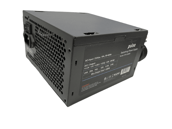
Now, probably the most fiddly but most satisfying bit: installing the PSU and associated cables.
Refer to the installation guide that came with your case to find out exactly how to fit the PSU.
- Remove your PSU from its packaging together with the bundle of assorted cables.
- For this build, we’ll need just 3 cables: the main ATX_PWR cable (the largest connector), the ATX_12V_1 & 2 cables, plus the PCIe 8-pin connector for the Graphics Card*
- Stand the case on its feet for ease of access to each side.
- Depending on what type of case you purchase, fitting the actual PSU unit will vary. Ideally, you’ll want one that you can slide into the case from the outside by removing a simple bracket. This allows you to attach any cables that are not already fitted to the PSU (I.e., if you have a semi-modular PSU) and then route them through the access holes to the inside of the case for connecting up.
- Once you have your required cables connected to the PSU and partially routed through the case cable access holes, push/insert the PSU all the way into the case and secure it in place with the 4 screws provided.
- Now, looking into the case, find the cables that you partially fed through and connect them to the motherboard connections. These cables are designed to fit in one way only, so check carefully. Once you are sure of the correct orientation for each, press to engage the cable connector with the motherboard socket until you hear it click. NOTE: The main ATX_PWR cable can be tough to plug in and usually requires quite a firm push – be careful not to flex the motherboard too much when doing this.
- The PCIe cable can be left loose until we’ve fitted the Graphics Card in the next step.
Graphics Card (GPU)
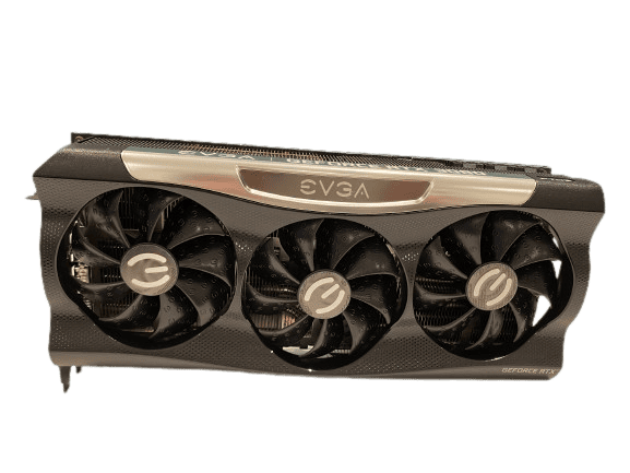
Nearing the end of the build now with the installation of the graphics card.
- Remove the GPU from its packaging and lay it down on its box, ready for installation.
- Lay the case on its side so that you have full access to the inside, ready to add the GPU.
- Take the GPU and hold it in the case roughly where it will be fitted, i.e., over the PCIe slot nearest to the CPU Heatsink and Fan assembly. Make note of which two of the metal slot covers (each secured by a single screw) need to be removed to create space for the GPU.
- Put the GPU back on the box and unscrew/remove the two slot covers on the case.
- Hold the GPU in the case over the PCIe slot, line it up carefully, and firmly push the card into the slot on the motherboard until you hear a click.
- Now use the two screws you removed earlier to secure the GPU in place by screwing them in the two vacated holes from the slot covers.
- Finally, plug in the PCIe power cable(s) to the GPU, noting the correct orientation.
Tidying Up
Now that all parts are fitted and connected, the last step is to tidy up the cabling with the cable ties.
Common sense is all that’s required here, tying up cables into neat bundles where appropriate to keep everything looking neat and out of the way of moving parts like cooling fans.
- Don’t forget to tidy the cabling at the rear of the case, making use of the cable tie points to secure cables in place.
- Excess cables can usually be pushed into empty spaces, like behind the PSU at the rear.
- Carefully snip the ends of each cable tie, removing any excess that was not used – it looks much neater.
- Once done, you can place the side panels back on and secure with the provided screws.
It might take a good 20 minutes or so, but the final look will be well worth the time spent.
Pat yourself on the back for a job well done!
Testing Your New PC Build
Now for the moment of truth!
- Connect up your freshly built PC tower to a mouse, keyboard, and suitable monitor (your monitor will need to have either a DisplayPort port or HDMI port).
- Connect the monitor to a port on your new graphics card.
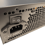
- Plug in the power cable to the back of the PC and flick the power switch next to the power cable socket to ‘On’.
- Turn the PC on by pressing the power button at the front of the computer
- If all is ok, you should get a screen displaying the BIOS; often, it will ask you to accept some settings and reset/reboot as it has just detected a new processor. Accept and proceed.
- The system will reboot into the BIOS on the next restart.
- Hold in the power button on the top of the PC to turn it off.
- If everything worked ok, congratulations! You’ve just built yourself a Gaming PC!
Installing Windows
The very last step is to install Windows (10 or 11, depending on your preference) so that you can get gaming!
You’ll need the use of another Windows computer to be able to download the Windows software onto a flash drive (You need a minimum of 8 GB, but I would recommend going for at least 16 GB).
The following steps assume you’ll be loading Windows 11, but the steps for Windows 10 are very similar if you decide to go down that route.
Once you have your flash drive, insert it into a USB port on the Windows computer and follow these steps:
- Go to: https://www.microsoft.com/en-gb/software-download/windows11/.
- Under ‘Create Windows 11 Installation Media’ click the blue ‘Download Now’ button
- Click the mediacreationtool.exe file download to start.
- Click ‘Accept’ on the license page.
- Click ‘Next’.
- Make sure the USB flash drive radio button is selected and click ‘Next’.
- Your Flash Drive should now be shown. Click ‘Next’.
- Windows 11 will now download and then create the bootable Windows 11 install media onto your Flash Drive.
- Click ‘Finish’ and remove your Flash Drive.
To install Windows 11 onto your new Gaming PC:
- First, insert your bootable Windows 11 Flash Drive into a USB port on your new computer.
- Turn on your computer.
- It may take a few minutes at first, but you should see the Windows egg timer (little dots going around in a circle) start-up to indicate that Windows is getting going.
- From here, you can simply follow the prompts to install Windows 11, entering your license code when prompted.
Enjoy your new Gaming PC!
Conclusion
Building a great gaming PC for $1000 by yourself is absolutely doable and, with our step-by-step guide, hopefully a bit easier, too. All you need is common sense, some simple tools, and a bit of patience.